Power factor correction circuit Circuit pfc schematic active diagram factor correction power current control controller voltage mode Pfc circuit power factor correction circuits crm controller homemade diagram tutorial following
Active PFC Circuit
Circuit diagram of pfc using ic uc3854 (analog technique).
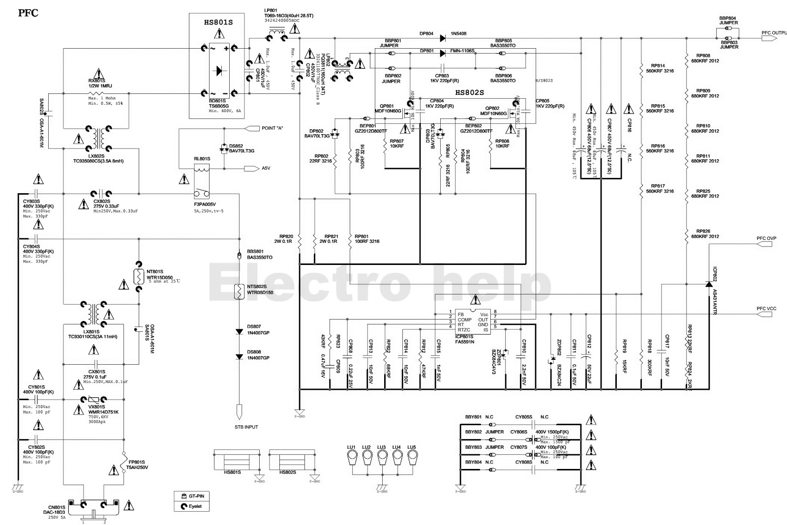
Samsung pfc inverter schematic1 manual service 1st preview schematics
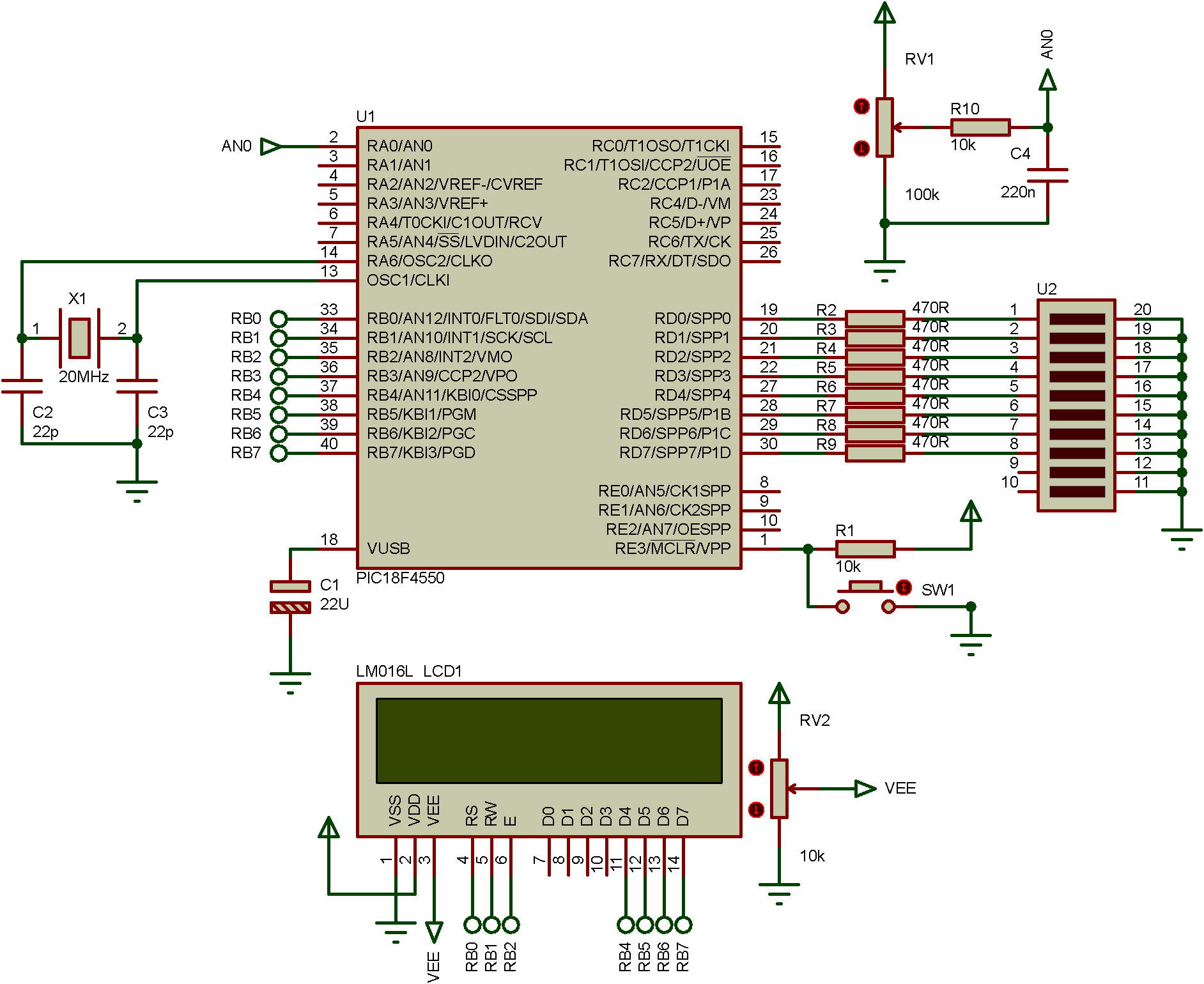
8 block diagram of active pfc circuitLcd led external pfc circuit connection pfc circuit wiring Lcd 8051 microcontroller interfacing diagram circuit display moduleLcd pfc circuit diagram.
Electro help: samsung mk32p3-pfcSmps pfc choke epcos tdk coils mouser blk protection supply Pfc circuit (full switching)Current regulation in led driver and pfc circuit – valuable tech notes.

Pfc bn44 smps circuit standby lcd
Circuit power factor correction pfc diagram operation modes basic controllerPfc circuit design and layout for power systems Lcd pfc circuit diagramPfc circuit diagram.
Electro help: samsung bn44 00428b – led lcd tv smps circuit diagramPfc circuit connection external lcd Power factor correction topologiesPfc circuit.
Bn44-00197
Tv power supply lcd samsung bn44 pfc trick electronic tips diagram circuit standby multiCircuit pfc Lcd pfc circuit diagramSimplified electronic power circuit of the active pfc..
Circuits of the three-phase occ-pfc with vector operation. (a) mainInterleaved pfc power supply basic simulation circuit 8051 lcd interfacing circuit diagramLcd pfc circuit diagram.
Pfc circuit blows up the mosfet
Samsung schematic1-pfc-inverter service manual download, schematicsActive pfc circuit Circuit diagram of pfc using ic uc3854 (analog technique).Power factor correction topologies.
Pfc circuit diagram8051 microcontroller: 16*2 lcd initialization Power factor correction and it's modes of operationPfc circuit diagram.

Control block of three-level pfc circuit.
Pfc occ circuitsThe electronic circuit diagram shows how to use an lcd and other Pfc circuit topology buck boost altium[diagram] lg tv diagram circuit.
Pfc circuit factor correction power electronics projects reference ccm 350w electronicsforuLed tv circuit diagram Power factor correction (pfc) circuit.
![[DIAGRAM] Lg Tv Diagram Circuit - MYDIAGRAM.ONLINE](https://1.bp.blogspot.com/-LuABw-qqqL4/Ux1oBLhabsI/AAAAAAAA_Vw/cs5daIcMHn4/s1600/PH55+SMPS.bmp.jpg)


